
Competition · 1 Nov 2026 · KFUPM ASCENT
Falcon-1 at TEKNOFEST 2026: building the rocket that took 2nd in A4 International
In September 2026, Falcon-1 went to the TEKNOFEST Rocket Competition final at the Hisar launch range in Aksaray, Türkiye, and finished second in the A4 International category.
It was entered by the Desert Falcons, a Saudi team of KFUPM students who are part of KFUPM ASCENT today, supported by engineers from Midana Company for Evaluation. A lot of what it taught us is going straight into ASCENT-H1. This post walks through the rocket using the team's Critical Design Review (CDR) and Flight Readiness Review (FRR) reports, and the photos taken along the way.
The brief
TEKNOFEST is Türkiye's aerospace and technology festival. For 2026, 2,212 teams applied to the rocket competition, and 73 reached the Group A finals, held from 7 to 13 September.
In A4 International, the organisers supply the motor. Everything else is the team's job: airframe, fins, recovery, avionics and a scientific payload. The rules are strict:
- The payload must weigh at least 4 kg, leave the rocket after apogee and come down under its own parachute with its own tracker.
- The rocket needs two independent flight computers: a commercial primary and a backup that the team designs and builds itself.
- Every design decision has to be backed by calculations, drawings, photos and test videos, across three written reviews (PDR, CDR and FRR), before the rocket is allowed near the range.
Falcon-1's declared target altitude was 3,210 m (10,531 ft).

Falcon-1 at a glance
| Length | 2,450 mm |
|---|---|
| Diameter | 114 mm |
| Structure | Aluminium airframe, couplers, bulkheads and four aluminium fins |
| Lift-off mass | 22.8 kg (15.8 kg without motor) |
| Declared target altitude | 3,210 m (10,531 ft) |
| Simulated apogee | 3,617 m |
| Top speed | about Mach 0.83 |
| Rail-exit speed | 31.5 m/s |
| Stability margin | 2.06 calibres at Mach 0.3 |
| Recovery | Three parachutes; hot gas generator separation |
| Payload | 4 kg scientific payload with its own parachute and tracker |
| Flight computers | SkyLogic V2 (primary) and a team-built ESP32 board (backup) |
Design values from the CDR OpenRocket model.
The flight plan
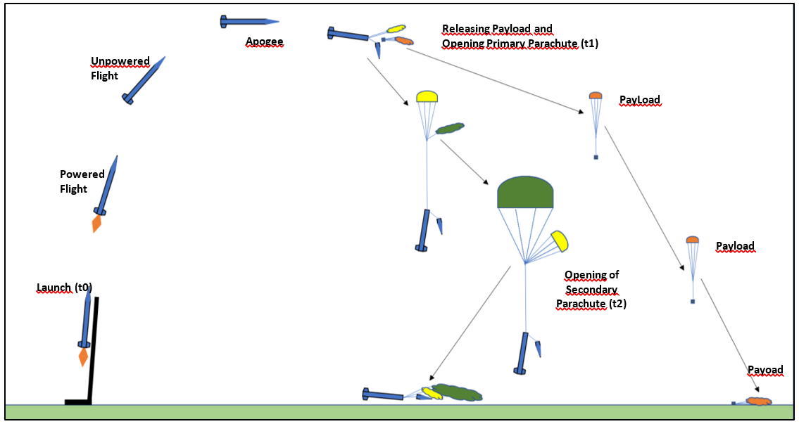
The competition fixes the shape of the flight, and each team fills in its own numbers. For Falcon-1, the CDR simulation gave:
- The motor burns out about 6.8 s into the flight, at roughly 1,340 m.
- The rocket coasts to apogee at about 27 s and 3,617 m.
- Two seconds after apogee, once the rocket has tipped over, a hot gas generator drives a piston that shears the retaining pins and pushes out the payload and a small primary parachute.
- The rocket falls under that primary parachute until about 543 m above the ground, where the large secondary parachute opens.
- The rocket lands at about 6 m/s. The payload, on its own parachute, lands at about 7 m/s.
From composites to aluminium
At the preliminary design stage, Falcon-1 was a carbon-fibre and composite rocket. By the CDR it had become an aluminium one: the team rejected composites over manufacturing and rule-compliance uncertainty.
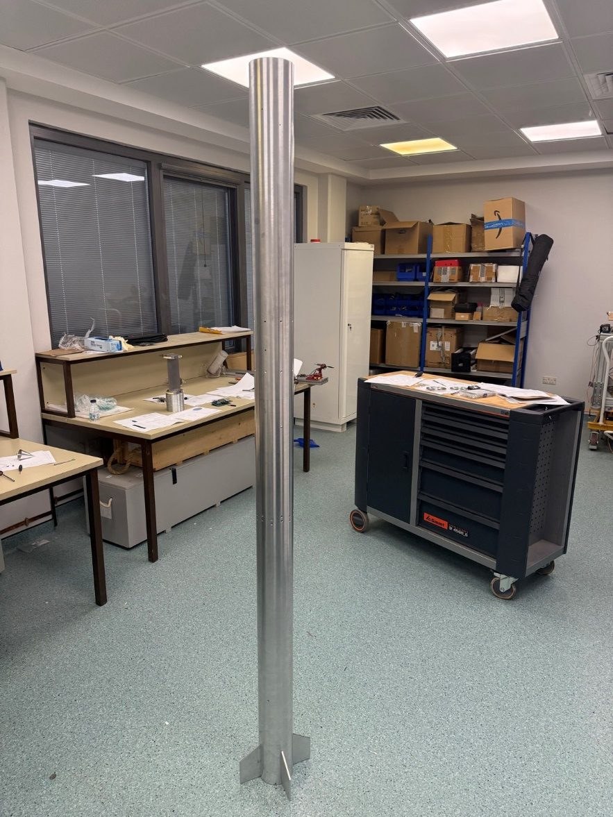
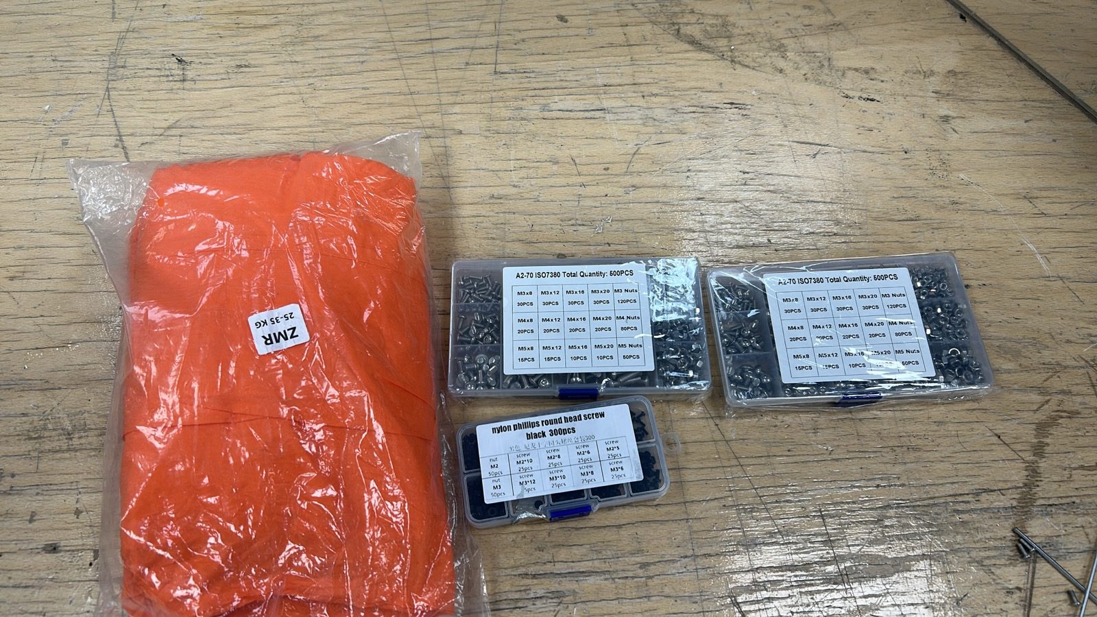
Choosing aluminium did not make the airframe easy. The first supplier the team found would only take large industrial orders, with a lead time of more than two months. Several local workshops then turned the job down: long, thin-walled tubes with tight limits on straightness, roundness and wall thickness are hard to make. One manufacturer finally took the work, and the body tubes (114.3 mm across with a 2.11 mm wall) were among the last parts to arrive.
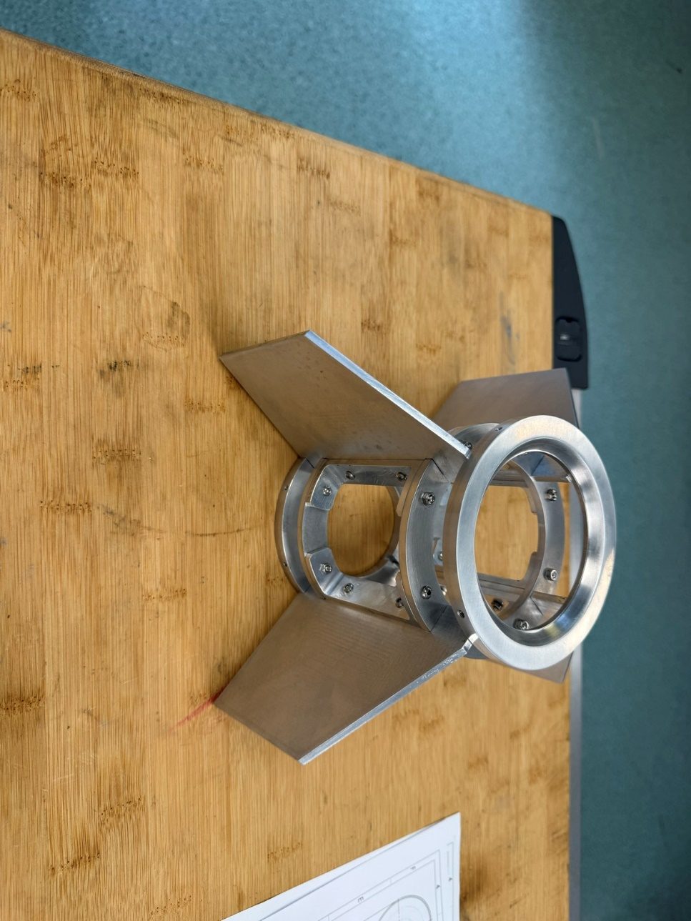
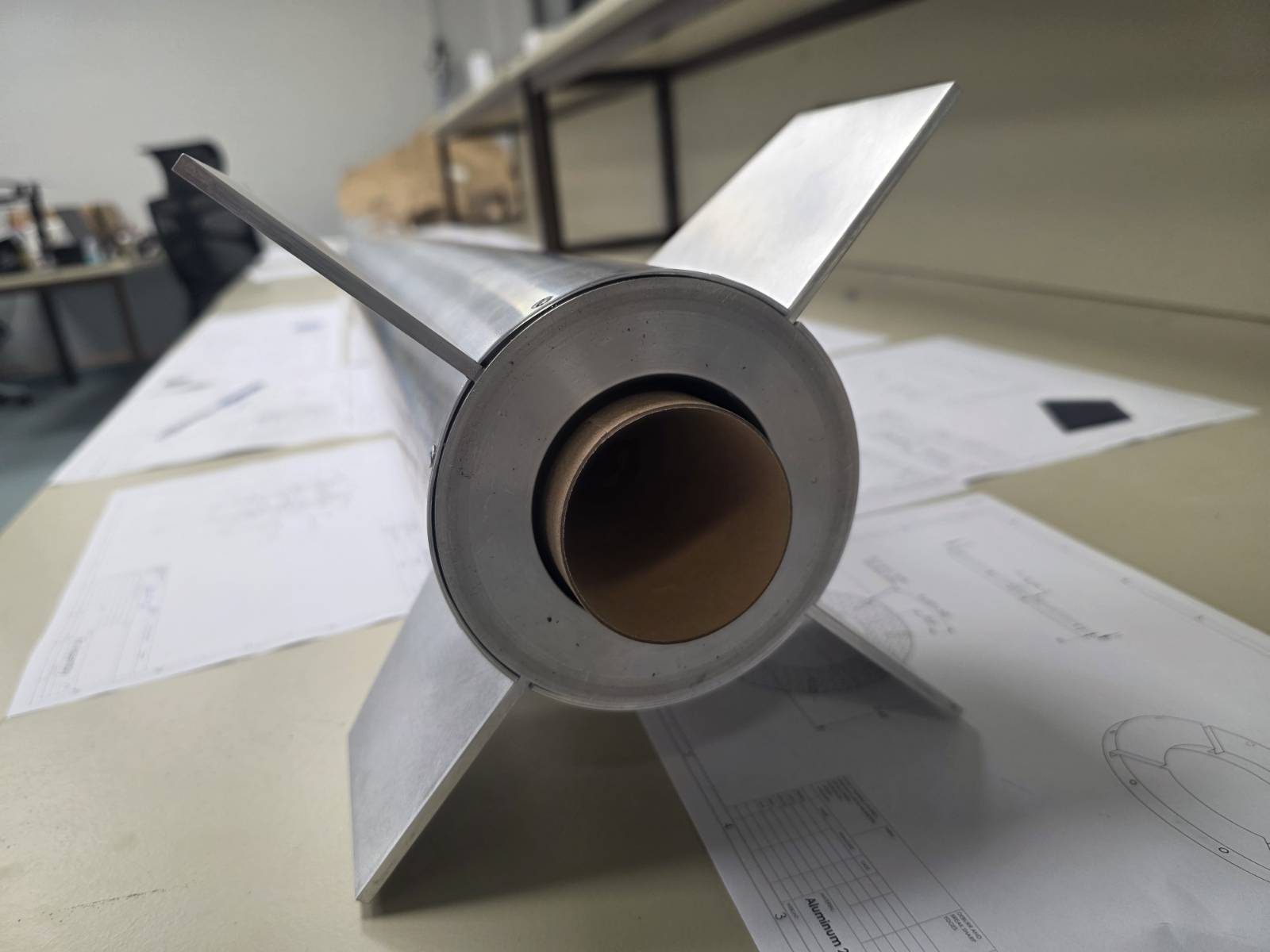
The four fins are 4 mm aluminium 2014-T4 plates, held by brackets, 32 M3 bolts and two centring rings in a fin can at the rocket's aft end. In the lab, a cardboard stand-in marked where the motor would sit, because in A4 the real motor goes in last, at the range, under the organisers' procedures.
Weigh everything
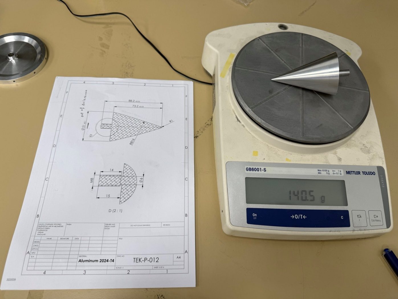
The FRR photos show the same routine for every part, from the nose tip to the payload disks: drawing on the bench, part on the scale, number in the mass budget. The measured masses go back into the OpenRocket model, so the predicted centre of gravity, stability and apogee describe the real rocket rather than the CAD.
Checking the numbers
OpenRocket handled the trajectory and stability. The design target was a rocket that is stable but not excessively over-stable, and the final model gave a static margin of 2.06 calibres at Mach 0.3.
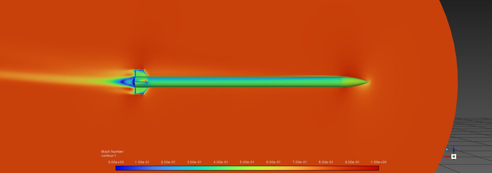
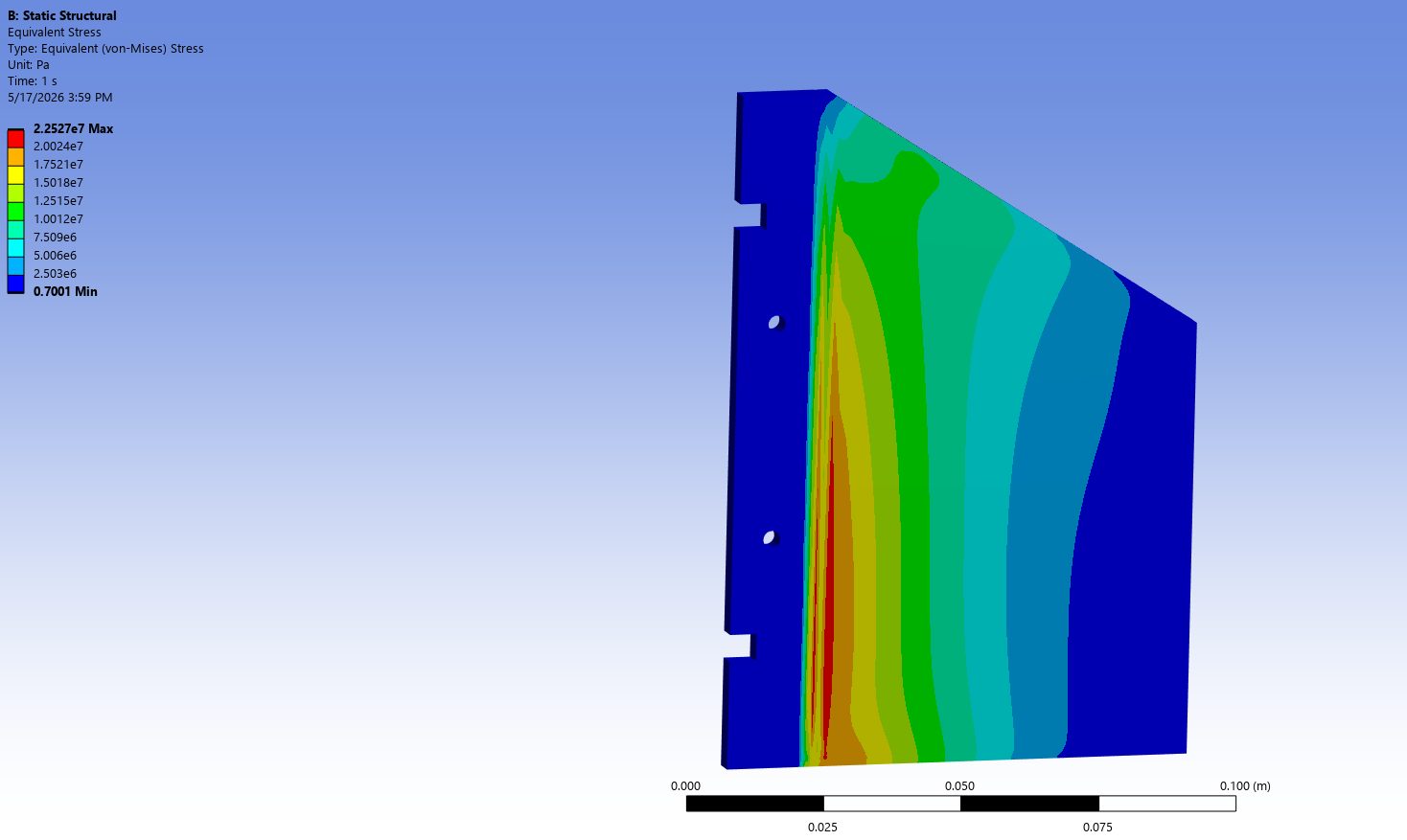
CFD in ANSYS Fluent at Mach 0.828, close to the predicted top speed, checked drag and loads at 0° and at a 10° angle of attack. Hand calculations and finite-element models covered the airframe, bulkheads, shear pins, screws and fins. The fins' peak stress in FEA was 22.5 MPa, and their estimated flutter speed of about 856 m/s is more than three times the rocket's predicted top speed.
Three parachutes, no friction fits
Recovery uses three parachutes:
- A 76 cm elliptical primary parachute steadies the rocket after separation.
- A 183 cm secondary parachute brings the rocket down for landing.
- A 91 cm payload parachute carries the payload on its own.
The short forward tethers are ¼-inch Kevlar. The main tether, which takes the biggest opening load, is 1-inch nylon webbing because it absorbs energy better. Each separation joint is held by three nylon shear pins rather than a tight friction fit, so it stays closed in flight and opens predictably when the gas generator fires. The opening-load checks gave factors of safety from about 5 on the main tether to more than 30 on the forward one.
The payload
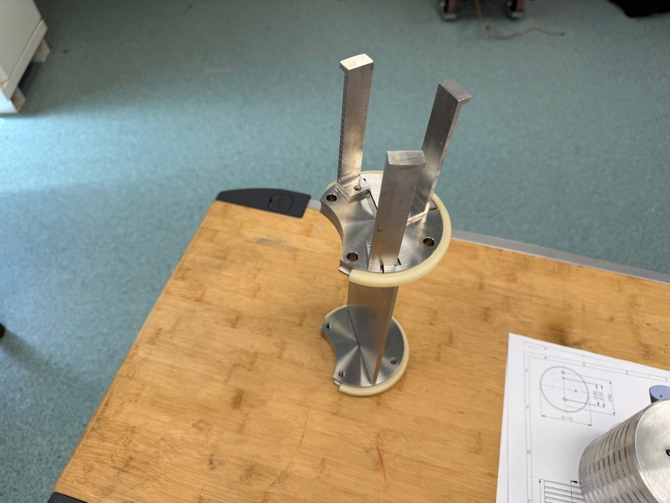
The scientific payload is a 4 kg module built from machined stainless-steel disks and plates clamped together on M8 rods and centred in the airframe by PTFE rings. Stainless steel was a deliberate choice: the structure itself supplies most of the required mass, so very little dead ballast is needed. It logs pressure, temperature, acceleration, altitude and GPS position, and sends its data to the ground over LoRa at 5 Hz or faster. A LILYGO T-Beam board handles GPS and radio, and a buzzer, a flashing light and an orange finish help the recovery crew find it.
The mechanical design stops the payload from sliding aft toward the motor under acceleration, while leaving it free to slide out forward at separation, with no cables crossing the joint.
Two flight computers, and one cancelled order
The plan was a commercial flight computer as primary and a team-built board as backup. The commercial unit was ordered early and was due on 11 July. On 14 July the order was cancelled and refunded.
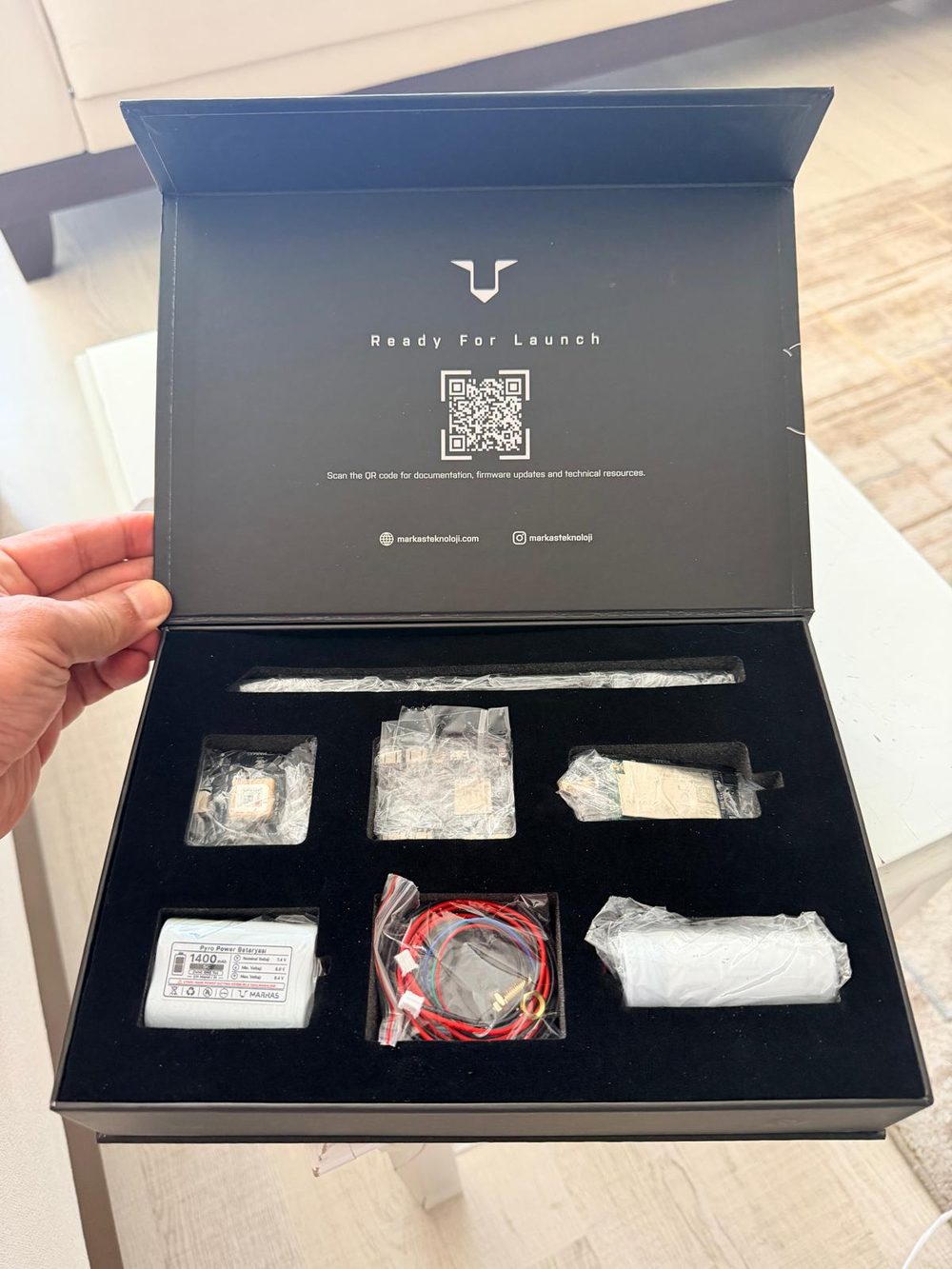
With the launch less than two months away, the team told the TEKNOFEST organisers. They pointed the team to Markas Teknoloji, a company founded by former TEKNOFEST competitors that makes the SkyLaunch flight-computer kit. The team bought two kits, and a friend of the team in Türkiye got them to Saudi Arabia in two days. One became the primary flight computer. The other is a spare that can also back up payload tracking. The SkyLogic V2's firmware was updated, and the unit was configured and checked against its SkyGround receiver before integration.
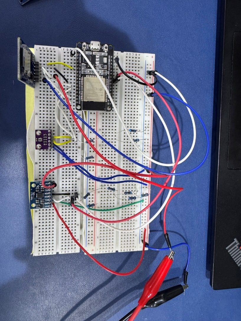
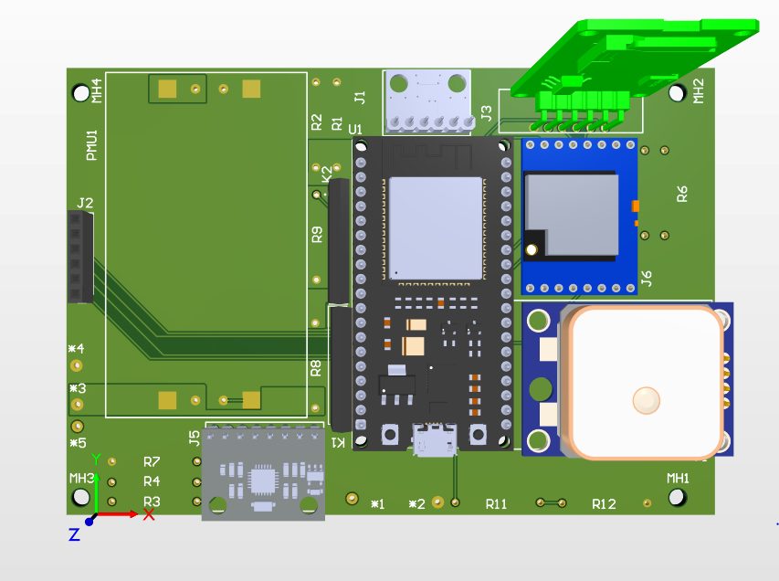
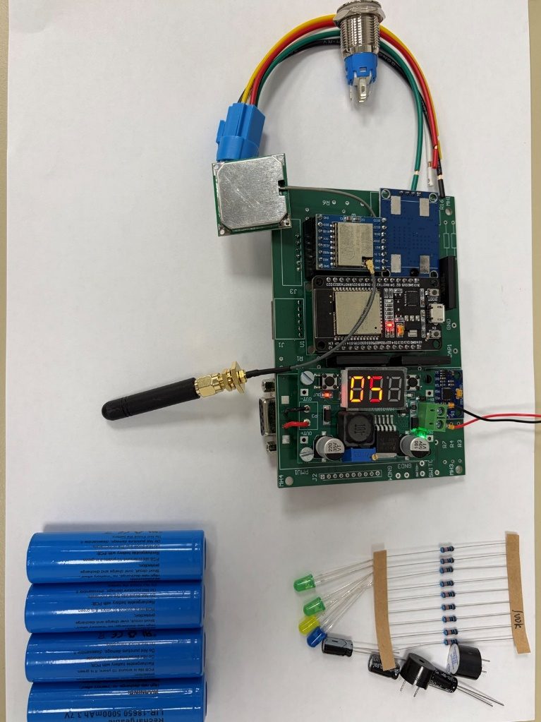
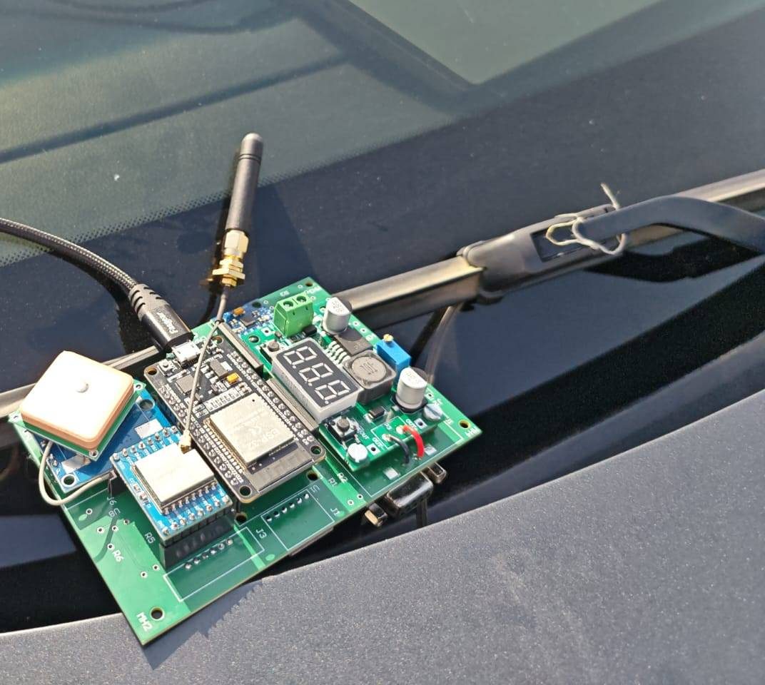
The backup computer is the team's own. It started on a breadboard and grew into a four-layer PCB built around an ESP32, with a BME280 pressure and temperature sensor, an MPU-6050 IMU, a u-blox NEO-6M GPS, a 433 MHz LoRa radio, microSD logging and the separation outputs. The assembled board was powered up, logged sensor and GPS data, and streamed LoRa packets to a ground station. One afternoon test at KAU in Jeddah logged 54.9 °C on the board's temperature sensor. A first range check with a small omni antenna reached about 200 m, with a Yagi antenna lined up for the long-range test.
What Falcon-1 taught us
- Order the long-lead parts first. The airframe tubes and the flight computer both came close to sinking the schedule. Start with the hardest parts to source, and find a second source before you need it.
- Buy the spare. Two SkyLaunch kits meant that one dead unit would not end the campaign.
- Weigh everything. A simulation is only as good as its mass budget.
- Own the avionics. Taking the backup computer from breadboard to a finished PCB in a few months built experience that carries over to every rocket after it.
- Treat the paperwork as engineering. Writing the CDR and FRR forced every number back to a drawing, a calculation or a photo. That is the habit we are bringing to ASCENT-H1 and FAR-OUT 2027.
The Desert Falcons
Thanks to the TEKNOFEST organisers, Markas Teknoloji, and everyone who helped get parts made and shipped in time.
Want to follow ASCENT-H1 on its way to FAR-OUT 2027? Join the team or support the mission.