
Aerostructures · 15 Oct 2026 · KFUPM ASCENT
Sizing ASCENT-H1's fins: stability, flutter and the tip-to-tip layup
Fins have two jobs on ASCENT-H1. They have to keep the rocket pointing where it is going, from the moment it leaves the rail until the motor burns out. And they have to survive the trip: 217 m/s (Mach 0.64) at peak, in the densest air of the flight, two seconds after lift-off.
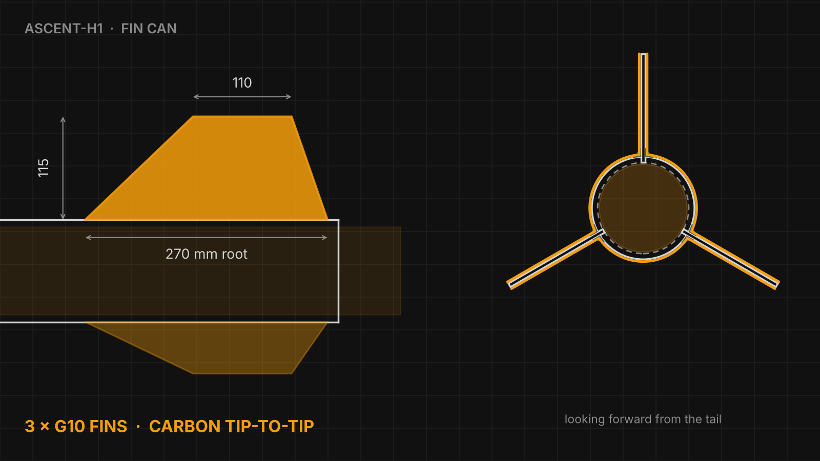
Our answer is three trapezoidal fins with 4 mm G10 cores and a two-layer carbon tip-to-tip overlay, mounted through the airframe wall onto the 98 mm motor tube. This post covers how we sized them and the flutter check that comes next.
The fins at a glance
| Number | 3, trapezoidal |
|---|---|
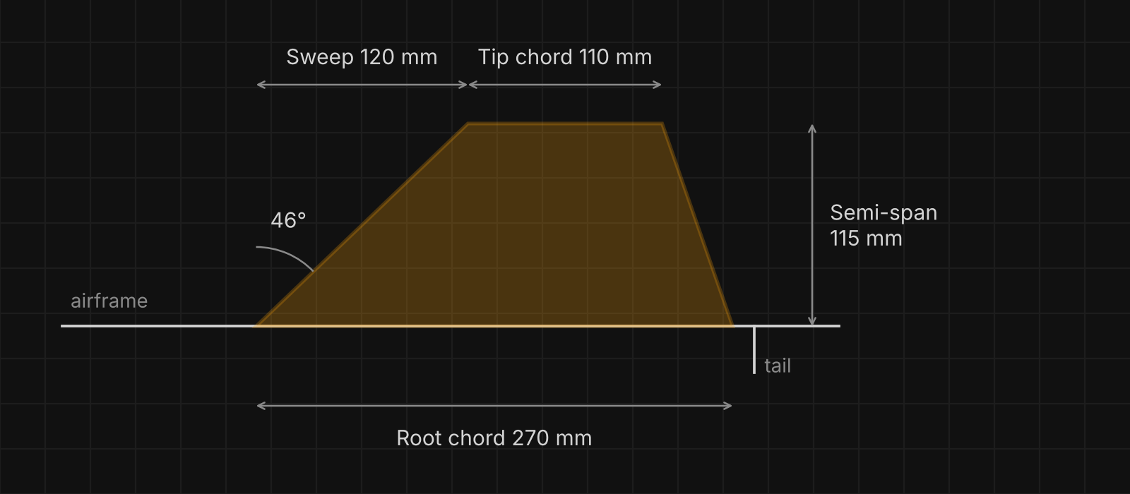
| Root chord | 270 mm |
| Tip chord | 110 mm |
| Semi-span | 115 mm |
| Leading-edge sweep | 120 mm (46°) |
| Area, each | 218.5 cm² |
| Aspect ratio | 0.61 |
| Taper ratio | 0.41 |
| Core | 4 mm G10 fibreglass |
| Overlay | Two layers of carbon fibre, tip to tip (4.5 mm thick overall) |
| Thickness / root chord | 1.5% for the core, 1.7% with the carbon |
| Mounting | Through the wall onto the 98 mm motor tube, with Aeropoxy fillets |
Stability: enough margin at the worst moment
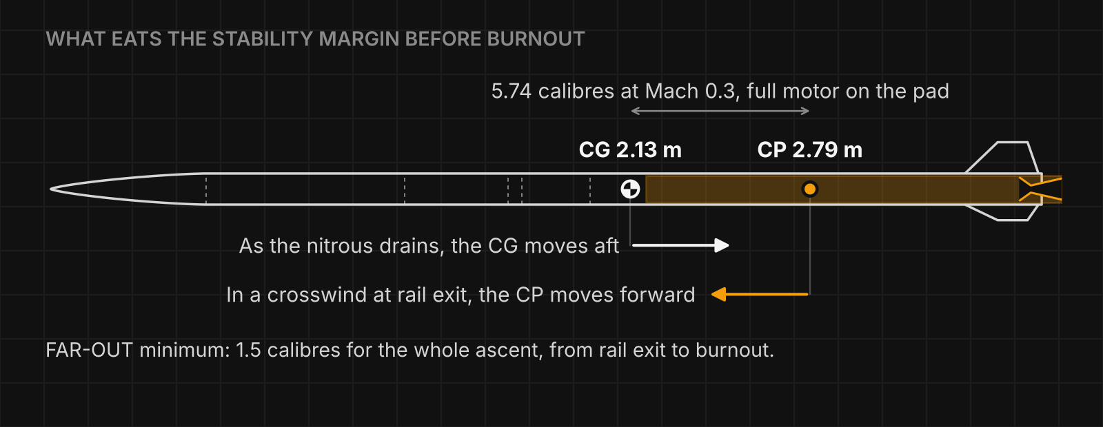
FAR-OUT requires a static stability margin of at least 1.5 calibres for the whole ascent, from rail exit to burnout. One calibre is one body diameter, 114 mm on ASCENT-H1, so the centre of pressure (CP) has to stay at least about 171 mm behind the centre of gravity (CG) the whole way up.
On the pad, with a full motor, our current OpenRocket model puts the CG at 2.13 m and the CP at 2.79 m from the nose tip: 5.74 calibres at Mach 0.3. That sounds generous, but two things eat into it before burnout:
- The CG moves aft. ASCENT-H1 flies a nitrous-oxide hybrid, and the nitrous drains out of a tank at the front of the motor as it burns. The motor's centre of gravity moves aft, and the rocket's CG slides back towards the CP.
- The CP moves forward in a crosswind. The rocket leaves the rail at only 30.5 m/s. A 10 mph (4.5 m/s) crosswind at that speed puts it at about 8° to the airflow, and at an angle the long body adds lift ahead of the fins, which pulls the CP forward.
So we sized the fins against the hard case, not the pad case: at least 1.5 calibres at rail exit in a 10 mph crosswind. FAR also limits the damping ratio to between 0.03 and 0.5 (0.05 to 0.3 suggested) and asks for the rocket to cope with gusts of up to 30 mph, so fin sizing means hitting a window, not just clearing a minimum.
The tip-to-tip layup
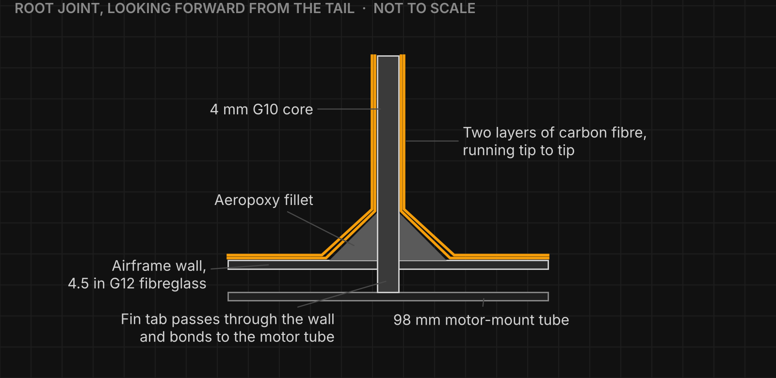
Each fin starts as a flat 4 mm G10 plate. The plate runs through a slot in the airframe wall and is bonded to the 98 mm motor-mount tube, with Aeropoxy fillets where the fin meets the airframe. The loads go into the motor section, not the airframe skin.
On top of that goes the tip-to-tip overlay: two layers of carbon fibre that run from the tip of one fin, down its side, across the airframe and up the next fin to its tip, all the way round. It does three things:
- It stiffens the fins in bending and twisting, which is exactly what raises their flutter speed.
- It thickens them, from 4 mm to 4.5 mm.
- It ties the three fins and the airframe into one structure. FAR's flutter calculation assumes the fins are rigidly fixed to the airframe, and its rules say plainly that fins "should not be wobbly or loose". The overlay helps make that assumption true.
Flutter: the check that comes next
Flutter happens when air flowing over a fin starts it bending and twisting, and that motion feeds the aerodynamic forces instead of damping them out. Below the flutter speed, a disturbance dies away. Above it, the oscillation grows until the fin fails. The worst case for ASCENT-H1 is maximum velocity, 217 m/s at 2.1 s, low over the 620 m FAR site where the air is densest.
In the standard NACA flutter estimate, flutter speed rises with the square root of the fin's shear modulus and with its thickness-to-chord ratio to the power 1.5. It also rises as aspect ratio falls and as the fin narrows more towards its tip, and it falls in the thicker air near the ground. Our fins are short and stubby (aspect ratio 0.61), which helps. They are also thin (1.5% to 1.7% of the root chord), which is why the carbon matters. Going from 4 mm to 4.5 mm alone raises the estimate by about 19%, before counting any extra stiffness from the carbon.
FAR-OUT gives teams its own flutter and divergence calculator, built on deliberately conservative methods. It needs the fins' shear modulus, either from FAR's materials library or measured by the team. For sandwich-style constructions, FAR asks teams to measure it themselves. A G10 core with carbon skins is not a material you can look up in a handbook, so that is what we will do: measure the shear modulus of our actual layup, then run FAR's calculator at the maximum-velocity point.
The flutter analysis is optional for our Initial Progress Update on 15 January 2027 and required for the Final Progress Update on 15 April 2027. We'll share the result here.
Read why ASCENT-H1 flies a COTS hybrid, or follow the build on the ASCENT-H1 page.